RSVG application in renewable energy station -- Shanxi Huancuishan photovoltaic power station SVG project
Project Name: Shanxi Huancuishan photovoltaic power station SVG project
application classification: photovoltaic power station
project requirements: harmonic filtering
2.1 Project overview
In March 2016, through the power quality monitoring system, it was found that the 35kV busbar harmonics of Huancuishan photovoltaic power station exceeded the standard. The Electric Power Research Institute then organized and carried out many special tests and analysis. In the power quality test process, the test points were selected from the secondary sides such as wayaokou station (35kV access point), high and low voltage side of main transformer and collector line side. It was found that the 5th and 7th harmonic current exceeding the standard was caused by photovoltaic power station, and the specific harmonic content is shown in Table 2.1.
Table 1 harmonic current measuring results of photovoltaic power station
|
harmonic current/A
|
35kV measurement result
|
10kV measurement result
|
|
|
Operation test on high voltage side of main transformer
|
National standard limits
|
Operation test on low voltage side of main transformer
|
National standard limits
|
|
3 次
|
2.61
|
4.5
|
9.45
|
27.38
|
|
5 次
|
15.36
|
4.68
|
54.05
|
27.38
|
|
7 次
|
6.03
|
3.64
|
22.46
|
20.53
|
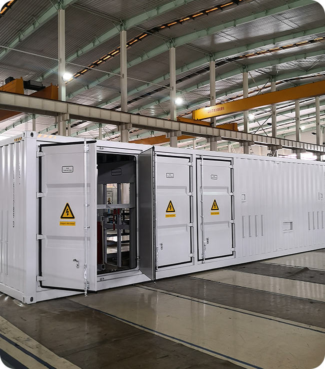
Considering the harmonic characteristics and design defects of Huancuishan photovoltaic power station, SVG is installed at the 10kV low-voltage side of the main transformer for centralized harmonic filtering. The project has been put into operation in 2018.
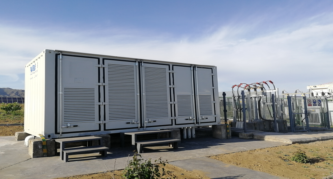
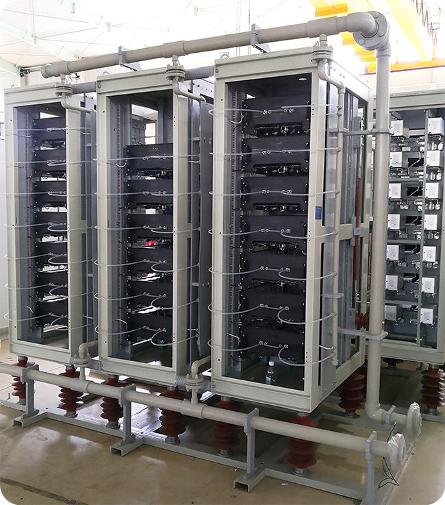
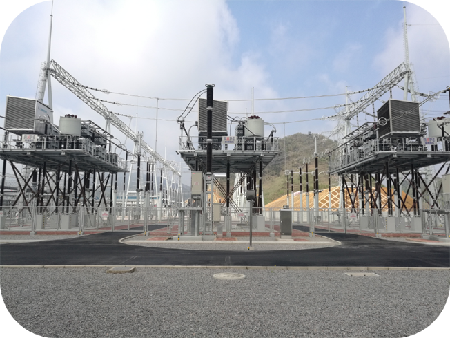
The actual device of SVG is shown in Figure 2-1.
2.2 Technical scheme
Taking into account the harmonic characteristics, engineering costs, construction difficulties and advanced technology of photovoltaic plants, it is recommended to adopt harmonic centralized filtering method, install SVG equipment on 10kV busbar, and automatically detect and filter 2nd~13th harmonics.
The SVG controller samples the grid voltage and current in real time, and realizes the detection function of load current harmonic component with the command current detection module. The reverse polarity of load current harmonic component is used as SVG command current. Through current closed-loop control and PWM modulation, SVG outputs the expected compensation current with reverse polarity of load harmonic current, so as to offset the harmonics in the grid.
2.2.1 SVG equipment information
SVG rated voltage: 10 kV
SVG rated capacity: ± 4 MVar
SVG connection mode: wye-connection
2.2.2 SVG main circuit topology
The topology of the main circuit is similar to Figure 1.2. After cascading, the SVG power unit modules are directly connected to the 10kV busbar through the connecting reactor.
2.3 Application Effect
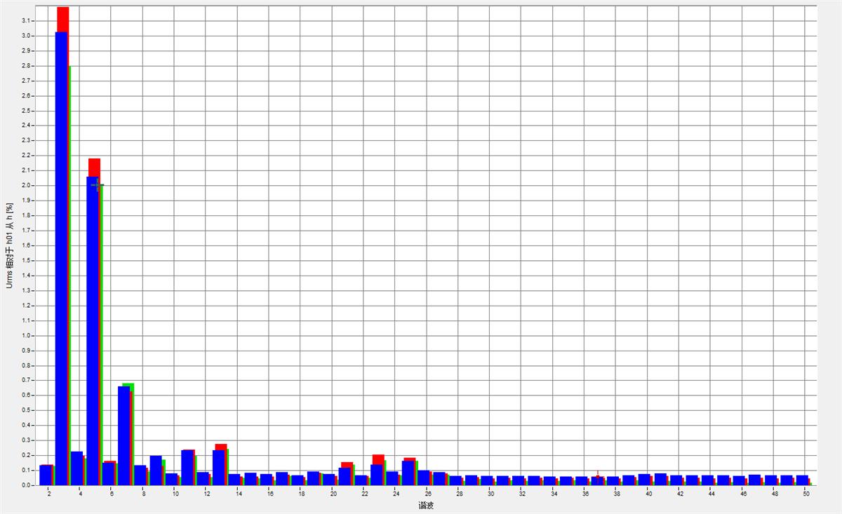
Figure 2.2 and figure 2.3 show the harmonic voltage spectrum of photovoltaic power station before and after SVG operation. Through the comparison, it can be concluded that after the SVG device is put into operation, the 35kV harmonic voltage is greatly reduced, and the filtering effect is remarkable.
、
Figure 2.2 harmonic voltage spectrum of PV station side without SVG
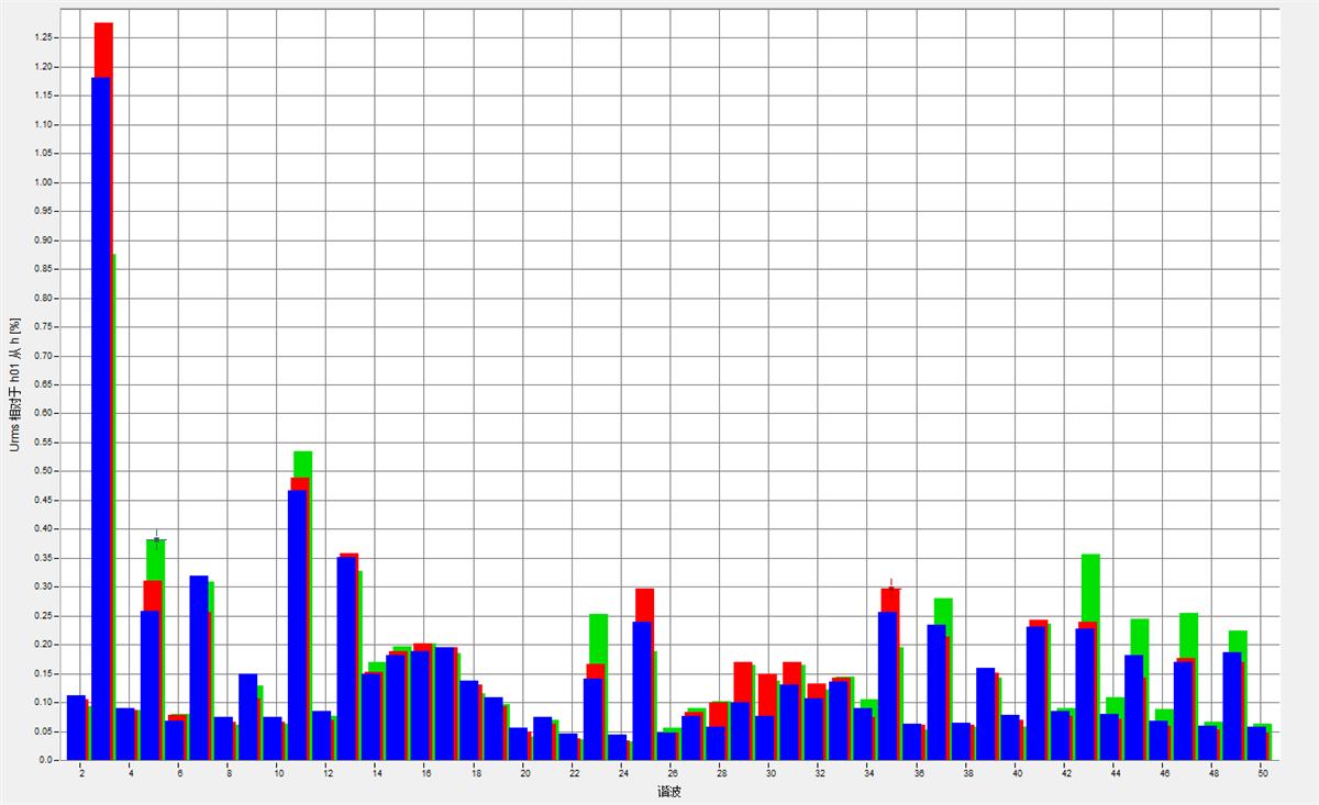
Figure 2.3 harmonic voltage spectrum of PV station side with SVG
Table 2 and table 3 respectively show the data comparison of 35kV harmonic voltage and harmonic current at the photovoltaic power station. When SVG is not put into operation, the total harmonic distortion rate of three-phase voltage at 35kV side and the content rate of 3rd, 5th and 7th harmonic voltage exceed the standard, and the total harmonic distortion rate of voltage reaches 6.27%, far beyond the national standard limit of 3.0%. After SVG is put into operation, the harmonic voltage content rate and total harmonic distortion rate meet the requirements of national standard.
Table 2. Comparison and analysis of 35kV side harmonic voltage (unit: %)
|
harmonic order
|
A phase
|
B phase
|
C phase
|
National standard limits
|
|
SVG
in operation
|
SVG out of operation
|
SVG in operation
|
SVG out of operation
|
SVG in operation
|
SVG out of operation
|
|
3
|
1.24
|
3.88
|
1.32
|
4.08
|
0.97
|
4.01
|
2.4
|
|
5
|
0.54
|
4.19
|
0.58
|
4.60
|
0.72
|
4.07
|
2.4
|
|
7
|
0.49
|
2.26
|
0.42
|
2.29
|
0.49
|
2.38
|
2.4
|
|
THDv
|
1.78
|
6.06
|
1.93
|
6.27
|
1.73
|
6.00
|
3.00
|
|
|
|
|
|
|
|
|
|
|
Before SVG was put into operation, the three-phase 5th and 7th harmonic currents at 35kV side exceeded the standard. After SVG was put into operation, each harmonic current does not exceed the standard, and SVG achieves good harmonic filtering effect.
Table 3. Comparative analysis of 35kV side harmonic current (unit: A)
|
harmonic order
|
A phase
|
B phase
|
C phase
|
National standard limits
|
|
SVG in operation
|
SVG out of operation
|
SVG in operation
|
SVG out of operation
|
SVG in operation
|
SVG out of operation
|
|
3
|
0.74
|
2.09
|
0.59
|
1.88
|
0.66
|
2.61
|
4.50
|
|
5
|
1.15
|
13.46
|
0.97
|
15.36
|
1.01
|
13.45
|
4.68
|
|
7
|
1.24
|
5.28
|
0.91
|
5.58
|
1.26
|
6.03
|
3.64
|
|
|
|
|
|
|
|
|
|
|
In this case, high voltage SVG device is used to filter harmonics, which is suitable for renewable energy power stations with harmonics exceeding standard limit.







 、
、

